
TMS320DM642 Video/Imaging Fixed-Point Digital Signal Processor
– 1024M-Byte Total Addressable External
• High-Performance Digital Media Processor Memory Space – 2-, 1.67-, 1.39-ns Instruction Cycle Time
• Enhanced Direct-Memory-Access (EDMA) – 500-, 600-, 720-MHz Clock Rate Controller (64 Independent Channels) – Eight 32-Bit Instructions/Cycle
• 10/100 Mb/s Ethernet MAC (EMAC) – 4000, 4800, 5760 MIPS – IEEE 802.3 Compliant – Fully Software-Compatible With C64x™ – Media Independent Interface (MII)
• VelociTI.2™ Extensions to VelociTI™ Advanced – 8 Independent Transmit (TX) Channels and 1 Very-Long-Instruction-Word (VLIW) Receive (RX) Channel TMS320C64x™ DSP Core
• Management Data Input/Output (MDIO) – Eight Highly Independent Functional Units With VelociTI.2™ Extensions:
• Three Configurable Video Ports
• Six ALUs (32-/40-Bit), Each Supports – Providing a Glueless I/F to Common Video Single 32-Bit, Dual 16-Bit, or Quad 8-Bit Decoder and Encoder Devices Arithmetic per Clock Cycle – Supports Multiple Resolutions/Video Stds
• Two Multipliers Support Four 16 x 16-Bit
• VCXO Interpolated Control Port (VIC) Multiplies (32-Bit Results) per Clock – Supports Audio/Video Synchronization Cycle or Eight 8 x 8-Bit Multiplies (16-Bit • Host-Port Interface (HPI) [32-/16-Bit] Results) per Clock Cycle
• 32-Bit/66-MHz, 3.3-V Peripheral Component – Load-Store Architecture With Non-Aligned Interconnect (PCI) Master/Slave Interface Support Conforms to PCI Specification 2.2 – 64 32-Bit General-Purpose Registers
• Multichannel Audio Serial Port (McASP) – Instruction Packing Reduces Code Size – Eight Serial Data Pins – All Instructions Conditional – Wide Variety of I 2S and Similar Bit Stream
• Instruction Set Features Formats – Byte-Addressable (8-/16-/32-/64-Bit Data) – Integrated Digital Audio I/F Transmitter – 8-Bit Overflow Protection Supports S/PDIF, IEC60958-1, AES-3, CP-430 – Bit-Field Extract, Set, Clear Formats
• Inter-Integrated Circuit ( I 2 – Normalization, Saturation, Bit-Counting C Bus™) – VelociTI.2™ Increased Orthogonality
• Two Multichannel Buffered Serial Ports
• L1/L2 Memory Architecture
• Three 32-Bit General-Purpose Timers – 128K-Bit (16K-Byte) L1P Program Cache
• Sixteen General-Purpose I/O (GPIO) Pins (Direct Mapped)
• Flexible PLL Clock Generator – 128K-Bit (16K-Byte) L1D Data Cache (2-Way • IEEE-1149.1 (JTAG) Boundary-Scan-Compatible Set-Associative)
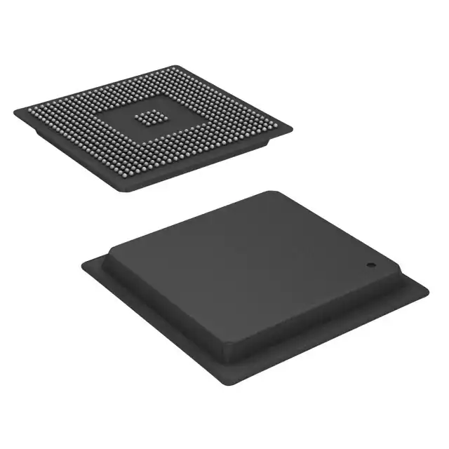
• 548-Pin Ball Grid Array (BGA) Package – 2M-Bit (256K-Byte) L2 Unified Mapped (GDK and ZDK Suffixes), 0.8-mm Ball Pitch RAM/Cache (Flexible RAM/Cache Allocation)
• 548-Pin Ball Grid Array (BGA) Package
• Endianess: Little Endian, Big Endian (GNZ and ZNZ Suffixes), 1.0-mm Ball Pitch
• 64-Bit External Memory Interface (EMIF)
• 0.13-µm/6-Level Cu Metal Process (CMOS) – Glueless Interface to Asynchronous
• 3.3-V I/O, 1.2-V Internal (-500) Memories (SRAM and EPROM) and
• 3.3-V I/O, 1.4-V Internal (A-500, A-600, -600, Synchronous Memories (SDRAM, SBSRAM, -720) ZBT SRAM, and FIFO)
TMS320DM642AZDKA6
| Part Number | Description |
|---|---|
| IS61LV5128AL-10TLI | SRAM - Asynchronous Memory IC 4Mb (512K x 8) Parallel 10 ns 44-TSOP II |
| 4D02WGJ0182TCE | |
| PK-11N40PQ | Buzzers Indicator, Internally Driven Piezo 5 V 5mA 4.1kHz 80dB @ 5V, 10cm Through Hole PC Pins |
| CLM2C-GCA-CXBB07A3 | Green 530nm LED Indication - Discrete 3.2V 4-PLCC |
| AO3401 | P-Channel 30 V 4A (Ta) 1.4W (Ta) Surface Mount SOT-23-3 |
| TA0638A | |
| CGRA4007-G | Diode Standard 1000 V 1A Surface Mount DO-214AC (SMA) |