
These instructions cover inserting pin and socket contacts into the cap and plug housings, mating the connectors, using test connectors, mounting the cap housing to a panel, and mounting the header to a printed circuit (pc) board. Reference to instructions for crimping the contacts, installing keying plugs, installing a strain relief, and extracting the contacts is included. Reference product part numbers are given in Figure 1. For detailed product description and application requirements, refer to application specification 114-1010. NOTE Dimensions in this instruction sheet are in metric units [with U.S. customary units in brackets]. Figures are not drawn to scale. Reasons for re-issue of this instruction sheet are provided in Section 4, REVISION SUMMARY.
1. ASSEMBLY 1.1. Inserting Contacts and Keying Plugs (Plug and Cap Housings) NOTE Split pin contacts are recommended for use in housings having 6, 9, 12, and 15 circuits to reduce mating force. Grounding pin contacts (2.54 mm [.100 in.] longer than standard pin contacts) are designed for a mate first, break last (MFBL) grounding application. Programmable socket contacts are designed to accept 110 series FASTON* receptacle terminals.
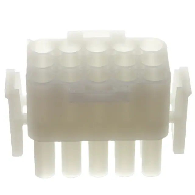
1-480710-0
| Part Number | Description |
|---|---|
| IS61LV5128AL-10TLI | SRAM - Asynchronous Memory IC 4Mb (512K x 8) Parallel 10 ns 44-TSOP II |
| 4D02WGJ0182TCE | |
| PK-11N40PQ | Buzzers Indicator, Internally Driven Piezo 5 V 5mA 4.1kHz 80dB @ 5V, 10cm Through Hole PC Pins |
| CLM2C-GCA-CXBB07A3 | Green 530nm LED Indication - Discrete 3.2V 4-PLCC |
| AO3401 | P-Channel 30 V 4A (Ta) 1.4W (Ta) Surface Mount SOT-23-3 |
| TA0638A | |
| CGRA4007-G | Diode Standard 1000 V 1A Surface Mount DO-214AC (SMA) |